Lab 1
Subteam 1: Felicia, Ben, Ian
Subteam 2: Michael, Ria
Materials:
- 2 Parallax Continuous Rotation Servos
- 3000 Ω potentiometer
- Robot chassis
- 2 wheels
- Ball bearing (w/ housing)
- Breadboard
- LEDs
- 300 Ω Resistor
The purpose of this lab was to familiarize the team with the functionality of the Arduino Uno, the Arduino IDE, and the Arduino’s I/O capabilities.
The tasks we set out to complete included:
- Blinking an external LED
- Controlling various systems via potentiometer
- Assembling an autonomously-operated robot
After retrieving the necessary components, we connected our Uno to the Arduino IDE and uploaded the Blink example program to it. The function of this program is to cycle an on-board LED on and off every second.
Original blink code: (not ours!)
// the setup function runs once when you press reset or power the board
void setup() {
  // initialize digital pin LED_BUILTIN as an output.
  pinMode(LED_BUILTIN, OUTPUT);
}

// the loop function runs over and over again forever
void loop() {
  digitalWrite(LED_BUILTIN, HIGH);   // turn the LED on (HIGH is the voltage level)
  delay(1000);                       // wait for a second
  digitalWrite(LED_BUILTIN, LOW);    // turn the LED off by making the voltage LOW
  delay(1000);                       // wait for a second
}
A video of the uploading process onto the Arduino Uno is shown for reference:
A video showing the on-board blinking mechanism is shown below. This confirmed that both the board and the Arduino IDE were functioning normally.
On-board LED blinking:
We modified the original blink code so that we could blink LEDs connected to the board’s other digital outputs. We connected the LEDs in series with 330Ω resistors to the Arduino’s digital output pins, in order to ensure that its max current wasn’t exceeded. The modifications are shown below:
Modifications to blink code:
void setup() {
  // initialize digital pin LED_BUILTIN as an output.
  pinMode(2, OUTPUT);
  pinMode(3, OUTPUT);
  pinMode(4, OUTPUT);
  pinMode(5, OUTPUT);
  pinMode(6, OUTPUT);
  pinMode(7, OUTPUT);
  pinMode(8, OUTPUT);
  pinMode(9, OUTPUT);
  pinMode(10, OUTPUT);
  pinMode(11, OUTPUT);
  pinMode(12, OUTPUT);
  pinMode(13, OUTPUT);
}

// the loop function runs over and over again forever
void loop() {
  digitalWrite(2, HIGH);   // turn the LED on (HIGH is the voltage level)
  digitalWrite(3, HIGH);
  digitalWrite(4, HIGH);
  digitalWrite(5, HIGH);
  digitalWrite(6, HIGH);
  digitalWrite(7, HIGH);
  digitalWrite(8, HIGH);
  digitalWrite(9, HIGH);
  digitalWrite(10, HIGH);
  digitalWrite(11, HIGH);
  digitalWrite(12, HIGH);
  digitalWrite(13, HIGH);
  delay(500);
  // wait for a second
  digitalWrite(2, LOW);   // turn the LED on (LOW is the voltage level)
  digitalWrite(3, LOW);
  digitalWrite(4, LOW);
  digitalWrite(5, LOW);
  digitalWrite(6, LOW);
  digitalWrite(7, LOW);
  digitalWrite(8, LOW);
  digitalWrite(9, LOW);
  digitalWrite(10, LOW);
  digitalWrite(11, LOW);
  digitalWrite(12, LOW);
  digitalWrite(13, LOW);
  delay(500);                       // wait for a second
}
First we tried it with one LED. Then we tried it with a bunch of LEDs. They all worked!
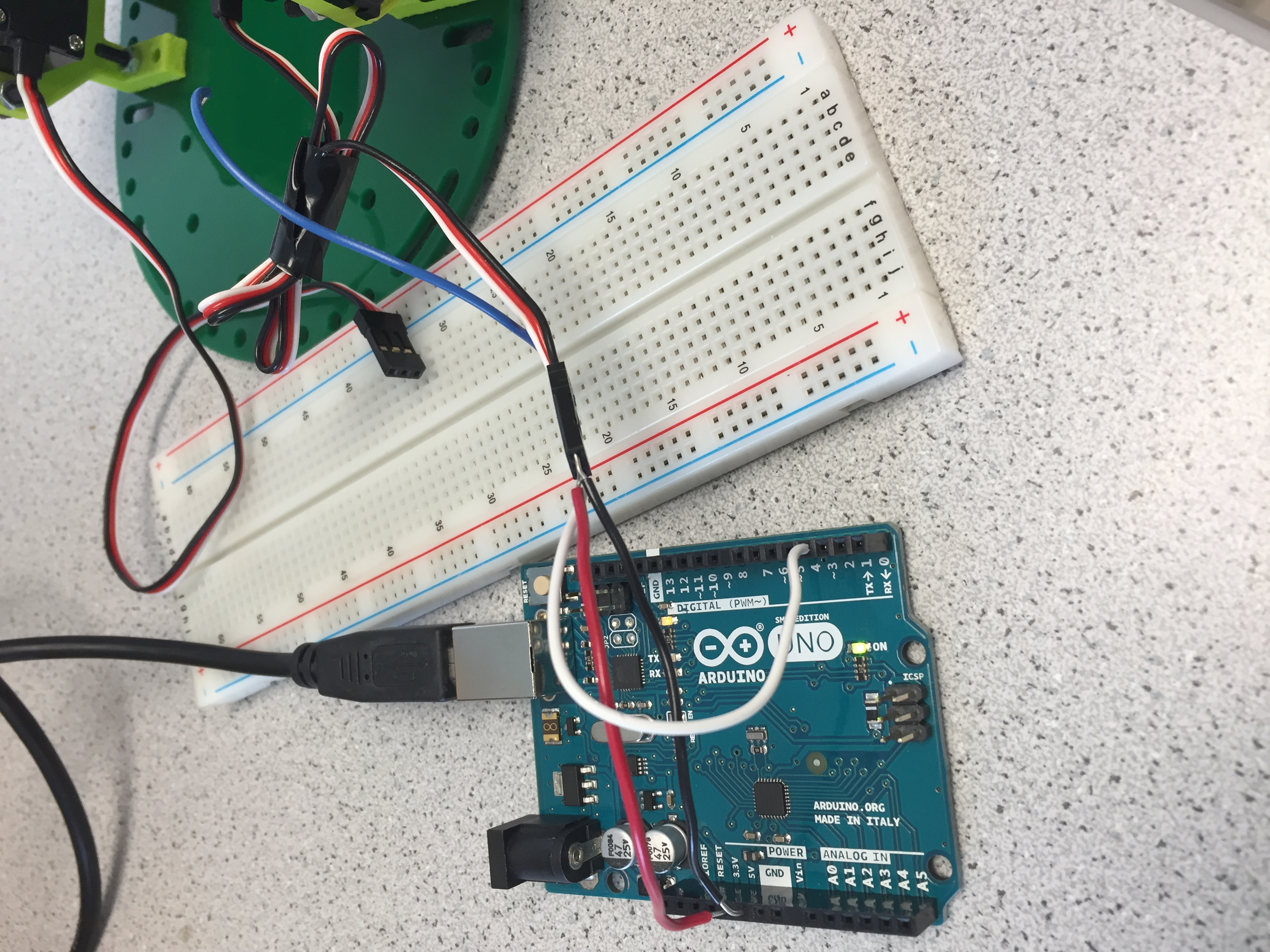
Having confirmed the functionality of the digital output pins, we turned next to the analog input pins. We tested these by using the potentiometer to create a simple voltage divider circuit, shown below:
Potentiometer Wiring Setup:
.png)
We initialized the serial monitor output to read the value of the analog pin every second:
Analog Read Function:
int analogPin = 0;
void setup() {
  // put your setup code here, to run once:
  Serial.begin(9600);
}

void loop() {
  // put your main code here, to run repeatedly:
  int val = analogRead(analogPin);
  float inV = val*.0049;
  Serial.print(inV);
  Serial.println (" V");
  delay(1000);
}
By adjusting the resistance of the potentiometer (turning the screw on top), we were able to adjust the voltage read by the analog input pins.
Potentiometer Analog Value Output:
We repeated this procedure for each analog input pin on the board to confirm functionality.
Next, we adapted this code to create an pseudo-analog output in the form of a pulse-width modulated (PWM) digital output. By continuing to use our potentiometer/voltage divider circuit as input to the Arduino, we were able to map our analog input value to a duty cycle for our PWM output.
The arduino’s so-called “analog output” is limited by the 8-bit bit depth of the digital output pin, restricting the possible output values to between 0 and 255. The conversion from the 10-bit input to the 8-bit output as well as the writing process is shown in our code below:
Analog Write Function:
int analogPin = 0;
int ledPin = 3;
void setup() {
  // put your setup code here, to run once:
  Serial.begin(9600);
}

void loop() {
  // put your main code here, to run repeatedly:
  int val = analogRead(analogPin);
  float convert = (float(val)/1023) * 255;
  int pwm = int(convert);
  Serial.println(val);
  Serial.println(pwm);
  analogWrite(ledPin, pwm);
  delay(250);
}
We put an LED and resistor in series with our PWM output pin, and by adjusting the potentiometer’s resistance, we were able to change the LED’s brightness.
Changing LED Brightness:
Next, we used these PWM output pins to drive our servos, which would eventually mobilize our robot. By including Arduino’s Servo library in the header of our program, we were able to write a range of rotation speeds to the servo. Once more, we implemented our potentiometer/voltage divider circuit here, allowing us to physically adjust the Servo’s rotation speed during operation.
Servo Wiring Setup:
Servo Motor Controls Using Potentiometer:
Finally, we programmed our robot to move in a square, its first autonomous task!
Implementation of Autonomous Task:
#include <Servo.h>

Servo servoL;
Servo servoR;
void setup() {
// put your setup code here, to run once:
Serial.begin(9600);
servoL.attach(3);
servoR.attach(9);
}

void loop() {
// put your main code here, to run repeatedly:
servoL.write(180);
servoR.write(0);
delay(1000);
servoL.write(180);
servoR.write(90);
delay(1000);
}
Watch our robot make a lil square!!