Milestone 1
Goals
The purpose of this milestone was to design a motion control system for our robot.
The tasks we set out to complete included:
- Getting our robot to successfully follow a line
- Getting our robot to successfully traverse a grid in a figure eight.
Additionally, we focused on:
- Developing a robust control system, and
- Getting our robot to complete these tasks at a reasonably high speed
Materials
The only materials used for this milestone that weren’t used in lab one were 3 QTR-1A reflectance sensors (datasheet here).
These sensors have three pins, VIN, GND, and OUT. Each sensor outputs a voltage at its OUT pin that corresponds with the lightness or darkness of the surface below it.
In our setup, the OUT pin of each sensor is tied to a separate analog input of the Arduino Uno controlling our robot. As such, each of these analog inputs will read in a value between 0 and 1023 corresponding to the lightness or darkness of the area under it.
Line Following
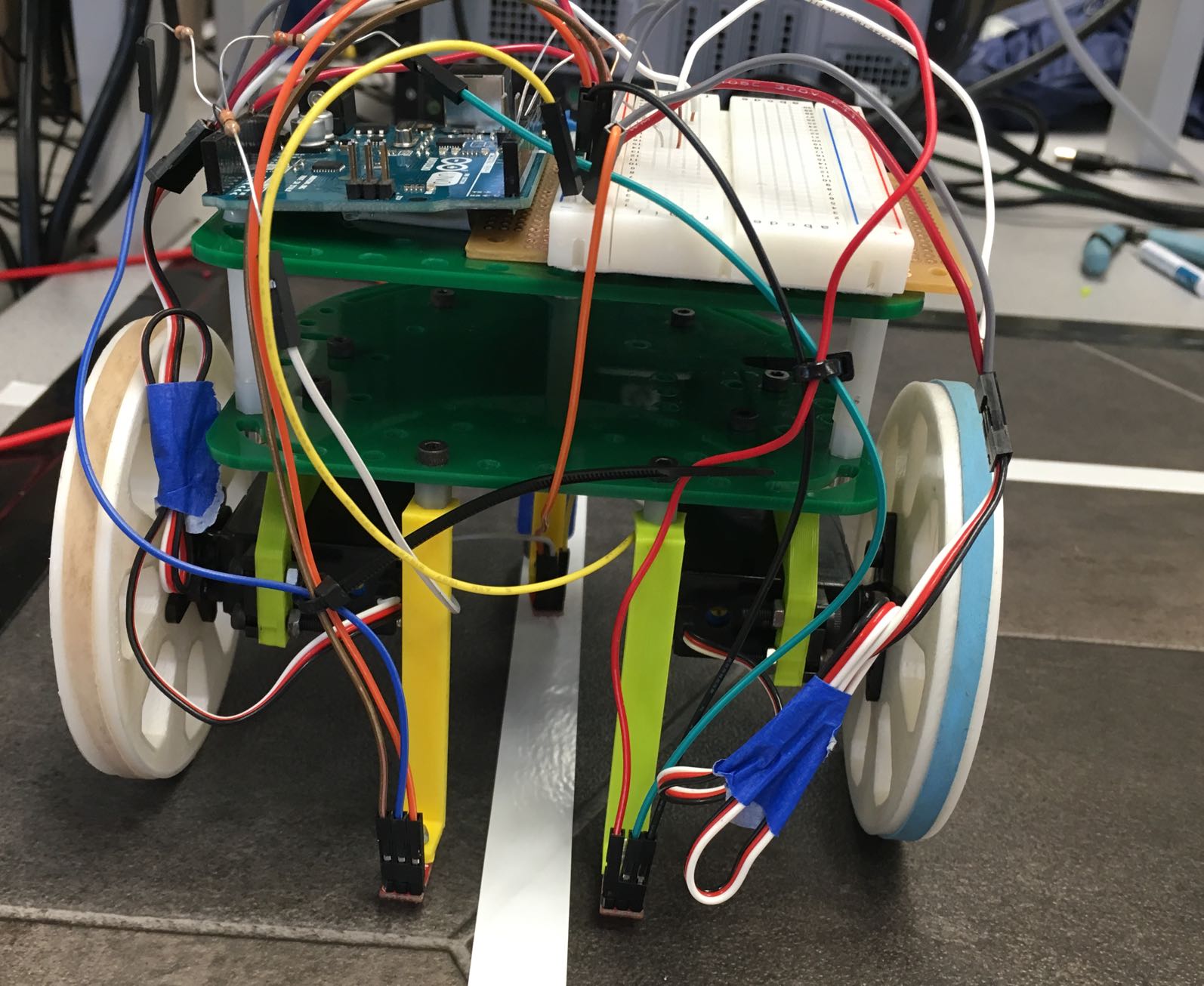
We equipped our robot with two line sensors in its front, designed to be far enough apart to straddle a line of electrical tape (see image below).
Our line following code is written with three cases in mind:
- If the robot detects that neither of its sensors are on the line, it will drive straight
- If the robot detects that its left sensor is on the line, it will veer left to correct course
- If the robot detects that its right sensor is on the line, it will veer right to correct courses
A snippet of this code is shown below (Please note: Our line-following code is written under the assumption that our robot will follow a grid of white tape on a black background. The threshold sensor values (300 in this case) will change under different circumstances.)
//Case: traveling along line --> drive straight
if (sensor_values[0] > 300 && sensor_values[1] > 300) { drive_straight();}

//Case: drifting off to the right --> correct left
else if (sensor_values[0] < 300) { veer_left(); }

//Case: drifting off to the left --> correct right
else if (sensor_values[1] < 300) { veer_right(); }
Some code from the helper functions drive_straight(), and veer_left() is shown below.
drive_straight() sets both wheels to rotate in the forward direction at a moderate speed.
void drive_straight(){
  servoL.write(95);
  servoR.write(85);
}
veer_left() increases the speed of the right wheelrelative to its speed set by drive_straight(), and rotates the left wheel backward. veer_right() is defined nearly identically to veer_left().
void veer_left(){
  servoL.write(80);
  servoR.write(55);
}
Check out our robot following this jagged line:
Figure Eight
This part of the milestone builds upon our line-following implementation to recognize intersections and perform 90 degree turns, and perform them at the appropriate junctions.
The intersection-detection was accomplished by simply noting when both the left front and right front sensors saw white. Under this condition, our code enters a series of switch/case statements to determine whether to turn left or right. Each turn is numbered, and depending on the intersection number, the robot will execute a specific case statement. After completing a turn, the number of interesections detected is incremented so it will advance to the next case statement on the next turn it sees.
At each intersection, the robot makes the following turns:
1) Left
2) Right
3) Right
4) Right
5) Right
6) Left
7) Left
The switch/case statements in our setup and loop are shown below:
//Case: reaches intersection
if (sensor_values[0] < 300 && sensor_values[1] < 300){
    Serial.println("Intersection!");
    switch(turn_num){
      case 0:turn_left(); break;
      case 1:turn_right(); break;
      case 2:turn_right(); break;
      case 3:turn_right(); break;
      case 4:turn_right(); break;
      case 5:turn_left(); break;
      case 6:turn_left(); break;
      case 7:turn_left(); break;
      default: stop_drive(); break;
    }

    turn_num += 1;    // increment number of turns

    if (turn_num == 8){ turn_num = 0;}   // reset number of turns after figure 8 completed
In order to complete a 90 degree turn, we use the third line sensor to tell the robot when to stop turning– the idea is that the robot will stop turning once the back sensor sees white again. However, to deal with the fact that for a short time before the robot completely leaves the first white line, the sensor will still see white, a delay is put in by waiting until a change from black to white is detected. Then, the turn is executed until the change from black to white is detected again.
This delay is implemented using a countdown variable that executes at the processing speed of the Arduino and is calibrated to the speed of the wheels that we chose. We can later optimize this countdown variable to increase the speed of our robot.
The sensor values are also read during each action– turning and line following–to ensure that the robot knows when to stop.
We implemented these turns using helper functions, which are shown below:
//HELPER FUNCTIONS

void turn_left(){
  while (countdown > 0) {
    servoL.write(87);
    servoR.write(35);
    countdown = countdown - 1;
  }

   while (sensor_values[2] > 300){
       servoL.write(87);
       servoR.write(35);
       sensor_values[0] = analogRead(A0);
       sensor_values[1] = analogRead(A1);
       sensor_values[2] = analogRead(A2);//delay(500);
       Serial.println("Turning left!");
    }
   countdown = 8000;
}

void turn_right(){
  while(countdown > 0){
         servoL.write(105);
        servoR.write(93);
        countdown = countdown -1;
  }
  while (sensor_values[2] > 300){
        servoL.write(105);
        servoR.write(93);
        //delay(500);
            sensor_values[0] = analogRead(A0);
          sensor_values[1] = analogRead(A1);
         sensor_values[2] = analogRead(A2);
        Serial.println("Turning right!");
        Serial.println(sensor_values[2]);
    }

  countdown = 8000;
 }
}
Check out our robot trace a figure 8!!! (including some tough love to demonstrate course correction abilities)